
Depth Testing (Derinlik Testi)
Koordinat Sistemleri bölümünde 3B bir konteyner render etmiş ve arkada kalması gereken üçgenlerin öne geçmesini önlemek için bir depth buffer (z-buffer) kullanmıştık. Bu bölümde, depth buffer'ın sakladığı derinlik değerlerini ve bir fragment'ın önde olup olmadığını nasıl belirlediğini daha ayrıntılı inceleyeceğiz.
Depth buffer, tıpkı renk buffer'ı gibi (tüm fragment renklerini sakladığı için görsel çıktıyı oluşturur) fragment başına bilgi depolar ve renk buffer'ıyla aynı genişlik ve yüksekliğe sahiptir. Pencere sistemi tarafından otomatik olarak oluşturulan depth buffer, derinlik değerlerini 16, 24 veya 32 bit kayan nokta sayısı olarak saklar. Çoğu sistemde 24 bitlik hassasiyette bir depth buffer bulunur.
Depth testing etkin olduğunda OpenGL, bir fragment'ın derinlik değerini depth buffer'ın içeriğiyle karşılaştırır. Test geçerse fragment render edilir ve depth buffer yeni değerle güncellenir. Test başarısız olursa fragment atılır.
Depth testing, fragment shader çalıştıktan sonra (ve bir sonraki bölümde ele alacağımız stencil testinin ardından) ekran uzayında gerçekleşir. Ekran uzayı koordinatları, OpenGL'in glViewport fonksiyonuyla tanımlanan viewport ile doğrudan ilişkilidir ve fragment shader'daki yerleşik gl_FragCoord değişkeni aracılığıyla erişilebilir. gl_FragCoord'un x ve y bileşenleri fragment'ın ekran uzayı koordinatlarını temsil eder (sol alt köşe başlangıç noktası (0,0) olacak şekilde). Aynı değişken ayrıca fragment'ın derinlik değerini içeren bir z bileşeni de barındırır. Depth buffer içeriğiyle karşılaştırılan değer işte bu z değeridir.
Günümüz GPU'larının çoğu early depth testing (erken derinlik testi) adı verilen bir donanım özelliğini destekler. Erken derinlik testi, fragment shader çalışmadan önce derinlik testinin yapılmasına olanak tanır. Bir fragment'ın görünür olmayacağı (diğer nesnelerin arkasında kaldığı) açıksa, fragment'ı erkenden atabiliriz.
Fragment shader'lar genellikle oldukça pahalıdır; bu nedenle mümkün olan her yerde çalıştırmaktan kaçınmalıyız. Erken derinlik testi için fragment shader'a bir kısıtlama getirilir: fragment'ın derinlik değerine yazılmamalıdır. Bir fragment shader kendi derinlik değerine yazıyorsa erken derinlik testi mümkün olmaz; OpenGL, derinlik değerini önceden belirleyemez.
Depth testing varsayılan olarak devre dışıdır; etkinleştirmek için GL_DEPTH_TEST seçeneğiyle açmamız gerekir:
glEnable(GL_DEPTH_TEST); Etkinleştirildikten sonra OpenGL, derinlik testini geçen fragment'ların z değerlerini otomatik olarak depth buffer'a yazar; başarısız olanları ise atar. Depth testing etkinken her frame başında GL_DEPTH_BUFFER_BIT bayrağıyla depth buffer'ı da temizlemeniz gerekir; aksi hâlde önceki frame'in derinlik değerleri buffer'da kalmaya devam eder:
glClear(GL_COLOR_BUFFER_BIT | GL_DEPTH_BUFFER_BIT); Bazen tüm fragment'lara derinlik testi uygulanmasını isteyip, ancak depth buffer'ın güncellenmesini istemeyebilirsiniz — geçici olarak salt okunur bir depth buffer kullanmak gibi düşünebilirsiniz. OpenGL, glDepthMask ile GL_FALSE geçirerek depth buffer'a yazmayı devre dışı bırakmamıza olanak tanır:
glDepthMask(GL_FALSE); Bu ayarın etkili olması için depth testing'in etkin olması gerektiğini unutmayın.
Depth Test Fonksiyonu
OpenGL, derinlik testi için kullandığı karşılaştırma operatörünü değiştirmemize olanak tanır. Bu sayede OpenGL'in fragment'ları ne zaman geçireceğini veya atacağını ve depth buffer'ı ne zaman güncelleyeceğini kontrol edebiliriz. Karşılaştırma operatörünü (depth fonksiyonu) glDepthFunc çağrısıyla ayarlayabiliriz:
glDepthFunc(GL_LESS); Fonksiyon, aşağıdaki tabloda listelenen çeşitli karşılaştırma operatörlerini kabul eder:
GL_ALWAYS
Derinlik testi her zaman geçer.
GL_NEVER
Derinlik testi hiçbir zaman geçmez.
GL_LESS
Fragment'ın derinlik değeri saklanan değerden küçükse geçer.
GL_EQUAL
Fragment'ın derinlik değeri saklanan değere eşitse geçer.
GL_LEQUAL
Fragment'ın derinlik değeri saklanan değerden küçük veya eşitse geçer.
GL_GREATER
Fragment'ın derinlik değeri saklanan değerden büyükse geçer.
GL_NOTEQUAL
Fragment'ın derinlik değeri saklanan değere eşit değilse geçer.
GL_GEQUAL
Fragment'ın derinlik değeri saklanan değerden büyük veya eşitse geçer.
Varsayılan olarak GL_LESS kullanılır; bu, mevcut depth buffer değerine eşit veya daha yüksek derinlik değerine sahip tüm fragment'ları atar.
Depth fonksiyonunu değiştirmenin görsel çıktıya etkisini gösterelim. Işıksız, dokulu iki küp ve dokulu bir zemin içeren basit bir sahne kullanan kaynak kodunu buradan bulabilirsiniz.
Kaynak kodda depth fonksiyonunu GL_ALWAYS olarak değiştirdik:
Bu ayar, depth testing hiç etkinleştirilmemiş gibi davranır. Derinlik testi her zaman geçtiğinden, en son çizilen fragment'lar daha önce çizilenlerden önde görünür (gerçekte önde olmasalar da). Zemin düzlemini en son çizdiğimizden, zemin fragment'ları konteynerlerin önceden yazılmış fragment'larının üzerine yazılır:

Her şeyi tekrar GL_LESS olarak ayarlamak bize alışık olduğumuz sahneyi verir:

Depth Değer Hassasiyeti
Depth buffer, 0.0 ile 1.0 arasında derinlik değerleri içerir ve içeriğini izleyiciden görüldüğü şekliyle sahnedeki tüm nesnelerin z değerleriyle karşılaştırır. Görüntü uzayındaki bu z değerleri, projeksiyon frustum'unun near ve far düzlemleri arasında herhangi bir değer olabilir. Bu view-space z değerlerini [0,1] aralığına dönüştürmenin bir yoluna ihtiyacımız var; bunun bir yolu doğrusal dönüşümdür. Aşağıdaki (doğrusal) denklem, z değerini 0.0 ile 1.0 arasında bir derinlik değerine dönüştürür:
Fdepth=far−nearz−near
Burada near ve far, görünür frustum'u ayarlamak için projeksiyon matrisine sağladığımız değerlerdir (Koordinat Sistemleri bölümüne bakın). Denklem, frustum içindeki z derinlik değerini alır ve [0,1] aralığına dönüştürür. Z değeri ile karşılık gelen derinlik değeri arasındaki ilişki şu grafikte gösterilmektedir:
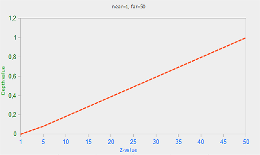
Tüm denklemlerin nesne yakın olduğunda 0.0'a, far düzlemine yaklaştığında 1.0'a yakın bir derinlik değeri verdiğine dikkat edin.
Ancak pratikte bu tür bir doğrusal depth buffer neredeyse hiç kullanılmaz. Projeksiyon özelliklerinden dolayı, 1/z ile orantılı doğrusal olmayan bir depth denklemi kullanılır. Bunun sonucu olarak z küçük olduğunda muazzam bir hassasiyet, z uzak olduğunda çok daha az hassasiyet elde ederiz.
Doğrusal olmayan fonksiyon 1/z ile orantılı olduğundan, 1.0 ile 2.0 arasındaki z değerleri 1.0 ile 0.5 arasında derinlik değerleri üretir — bu [0,1] aralığının yarısı demektir ve küçük z değerlerinde muazzam hassasiyet sağlar. 50.0 ile 100.0 arasındaki z değerleri ise [0,1] aralığının yalnızca %2'sine karşılık gelir. Near ve far mesafelerini de hesaba katan denklem şudur:
Fdepth=1/far−1/near1/z−1/near
Bu denklemi ezberlemek zorunda değilsiniz. Akılda tutmanız gereken önemli nokta şudur: depth buffer'daki değerler clip-space'te doğrusal değildir (projeksiyon matrisi uygulanmadan önce view-space'te doğrusallar). Depth buffer'daki 0.5 değeri, pikselin z değerinin frustum'un ortasında olduğu anlamına gelmez; vertex'in z değeri aslında near düzlemine oldukça yakındır! Bu doğrusal olmayan ilişkiyi aşağıdaki grafikte görebilirsiniz:
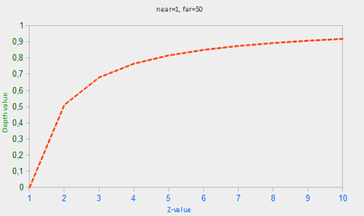
Gördüğünüz gibi derinlik değerleri, küçük z değerleri tarafından hâkim olarak belirlenir; bu da yakın nesneler için büyük hassasiyet sağlar. Z değerlerini dönüştüren denklem projeksiyon matrisine gömülüdür; bu nedenle vertex koordinatlarını view-space'ten clip-space'e, oradan da ekran uzayına çevirirken doğrusal olmayan dönüşüm otomatik olarak uygulanır.
Bu doğrusal olmayan denklemin etkisi, depth buffer'ı görselleştirmeye çalıştığımızda hemen belirginleşir.
Depth Buffer Görselleştirme
Fragment shader'daki yerleşik gl_FragCoord vektörünün z değerinin o fragment'ın derinlik değerini içerdiğini biliyoruz. Bu derinlik değerini renk olarak çıkarırsak, sahnedeki tüm fragment'ların derinlik değerlerini görüntüleyebiliriz:
Programı çalıştırırsanız muhtemelen her şeyin beyaz göründüğünü fark edeceksiniz; sanki tüm derinlik değerleri maksimum 1.0 değerindeymiş gibi. Peki neden derinlik değerlerinin hiçbiri 0.0'a yakın ve dolayısıyla daha koyu değil?
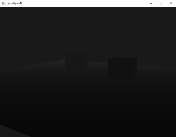
Önceki bölümde, ekran uzayındaki derinlik değerlerinin doğrusal olmadığını açıkladık: küçük z değerlerinde çok yüksek hassasiyet, büyük z değerlerinde düşük hassasiyet. Fragment'ın derinlik değeri mesafeyle birlikte hızla artar; bu nedenle neredeyse tüm vertex'lerin değerleri 1.0'a yakındır. Bir nesneye dikkatli bir şekilde çok yaklaşırsanız renklerin kararırken z değerlerinin küçüldüğünü görebilirsiniz:
Bu, derinlik değerinin doğrusal olmayan yapısını açıkça göstermektedir. Yakın nesneler, uzak nesnelerden çok daha büyük bir derinlik etkisine sahiptir. Sadece birkaç santimetre hareket etmek renklerin karadan tamamen beyaza geçmesine yol açabilir.
Bununla birlikte, doğrusal olmayan derinlik değerlerini doğrusal karşılıklarına dönüştürmek mümkündür. Bunun için projeksiyon sürecini yalnızca derinlik değerleri açısından tersine çevirmemiz gerekir: önce derinlik değerini [0,1] aralığından NDC'ye ([-1,1]) geri eşleriz, ardından projeksiyon matrisindeki doğrusal olmayan denklemi ters yönde uygularız. Sonuç doğrusal bir derinlik değeri verir.
Önce derinlik değerini NDC'ye dönüştürüyoruz:
Ardından elde edilen ndc değerini alarak doğrusal derinlik değerini elde etmek için ters dönüşümü uyguluyoruz:
Bu denklem, derinlik değerlerini doğrusal olmaktan çıkaran projeksiyon matrisinden türetilmiş olup near ile far arasında derinlik değerleri döndürür. Konuyla ilgilenenler için projeksiyon matrisini büyük ayrıntıyla açıklayan bu matematik yoğun makaleye bakabilirsiniz; denklemlerin nereden geldiği de orada açıklanmaktadır.
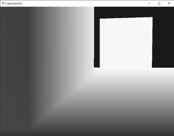
Ekran uzayındaki doğrusal olmayan derinliği doğrusal derinlik değerine dönüştüren tam fragment shader şudur:
Doğrusallaştırılmış değerler near'dan far'a kadar uzandığından, büyük çoğunluğu 1.0'ın üzerinde olacak ve ekranda tamamen beyaz görünecektir. main fonksiyonunda doğrusal derinlik değerini far'a bölerek sonucu [0, 1] aralığına çekiyoruz. Bu sayede frustum'un far düzlemine yaklaştıkça sahnenin kademeli olarak aydınlandığını görebiliriz — görselleştirme amacıyla bu yöntem daha kullanışlıdır.
Uygulamayı çalıştırdığımızda mesafeye göre doğrusal derinlik değerleri elde ederiz:
Renkler büyük ölçüde koyu görünür; çünkü derinlik değerleri near (0.1) ile far (100) arasında doğrusal olarak dağılır ve kameraya oldukça yakın durduğumuzdan düşük (koyu) derinlik değerleri elde ederiz.
Z-Fighting
İki düzlem veya üçgen birbirine o kadar yakın hizalanmış olduğunda depth buffer'ın hangisinin önde olduğunu belirleyecek kadar yeterli hassasiyeti olmayabilir. Bunun sonucu olarak iki şekil sürekli sıra değiştiriyor gibi görünür ve garip artefact'lara yol açar. Buna z-fighting denir; şekillerin üstte kalmak için birbirleriyle savaşıyormuş gibi görünmesinden adını alır.
Şimdiye kadar kullandığımız sahnede z-fighting'in fark edilebileceği birkaç nokta bulunmaktadır. Konteynerler tam olarak zeminin yüksekliğine yerleştirildi; bu da konteynerin alt düzleminin zemin düzlemiyle aynı düzlemde (coplanar) olduğu anlamına gelir. Her iki düzlemin derinlik değerleri aynıdır; dolayısıyla derinlik testi hangisinin doğru olduğunu belirleyemez.
Kamerayı konteynerlerden birinin içine taşırsanız etkiler açıkça görülür; konteynerin alt kısmı sürekli zigzag biçimde konteyner düzlemi ile zemin düzlemi arasında geçiş yapar:
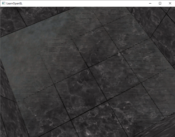
Z-fighting, depth buffer'larla sık karşılaşılan bir sorundur ve genellikle nesneler uzaklaştıkça (depth buffer büyük z değerlerinde daha az hassasiyet gösterdiğinden) daha belirgin hale gelir. Z-fighting tamamen önlenemez; ancak hafifletmek ya da sahnenizdeki z-fighting'i tamamen engellemek için bazı teknikler vardır.
Z-Fighting'i Önleme
İlk ve en önemli teknik, nesneleri yüzeyleri örtüşecek kadar birbirine yakın yerleştirmemektir. İki nesne arasına küçük bir boşluk bırakarak z-fighting'i tamamen önleyebilirsiniz. Konteynerler ve zemin örneğinde, konteynerleri pozitif y yönünde hafifçe yukarı taşımak yeterliydi. Bu küçük fark göze çarpmaz ve z-fighting'i tamamen ortadan kaldırır. Ancak bu yaklaşım, her nesne için elle müdahale ve sahnede z-fighting oluşturmayan tüm nesneleri doğrulamak için kapsamlı test gerektirir.
İkinci teknik, near düzlemini mümkün olduğunca izleyiciden uzağa taşımaktır. Near düzlemine yakınken hassasiyetin son derece yüksek olduğunu öğrenmiştik; dolayısıyla bu düzlemi uzaklaştırmak, frustum genelinde çok daha iyi hassasiyet sağlar. Ancak near düzlemini çok uzağa çekmek yakın nesnelerin kırpılmasına (clipping) yol açabilir, bu yüzden doğru değeri bulmak genellikle deneme yanılma gerektirir.
Üçüncü teknik ise daha yüksek hassasiyetli bir depth buffer kullanmaktır — biraz performans pahasına da olsa. Çoğu depth buffer 24 bit hassasiyetle çalışır; ancak günümüz GPU'larının büyük çoğunluğu 32 bit depth buffer'ı destekler ve bu hassasiyeti önemli ölçüde artırır. Ek performans maliyeti karşılığında derinlik testinde çok daha büyük bir duyarlılık kazanarak z-fighting'i belirgin biçimde azaltabilirsiniz.
Bu üç teknik, en yaygın ve uygulaması en kolay z-fighting önleme yöntemlerini oluşturur. Çok daha fazla çaba gerektiren ve yine de z-fighting'i tamamen yok etmeyen başka yöntemler de mevcuttur. Z-fighting sık rastlanan bir sorun olmakla birlikte, bu tekniklerin uygun bir kombinasyonunu kullandığınızda büyük ihtimalle fazlasıyla üstesinden gelebilirsiniz.
Orijinal kaynak: LearnOpenGL – Advanced-OpenGL/Depth-testing Türkçe çeviri: OpenGL Öğrenin projesi
Last updated